How to Run an Arduino for Years on a Battery
Last Update: Sun, Aug 13 2023
If you found this article after doing a search on Google, welcome! On this website you will find plenty of content around DIY home automation using open-source hardware. Enjoy the article!
For most of the Arduino tutorials you will find on this website, power is usually not an issue as the Arduino is powered by the USB cable coming from the computer. However, sometimes you want to build systems that are going to be autonomous and powered by a battery.
For example, you want to power a wireless motion detector just by using a set of batteries. The first idea would be to connect directly an Arduino board like the Arduino Uno R3 to a battery. Easy, right ? Well, it would work, but your battery would be depleted in a matter of days because some components like voltage regulators are always sucking power. So we need something better.
The first thing we need is to build our own Arduino system with just the minimal set of components. The second part is to optimise the software so that the system only consumes power when it is actually doing something. And that’s exactly what we will see in this article.
Hardware & Software Requirements
You need several components to build you own Arduino system. The main piece of this project is of course the microcontroller that will run your Arduino sketches, like the ATMega328. You will need a chip with the Arduino bootloader. Buy your chip with it, it will make your life easier.
In a previous project I used a FTDI breakout board to program the Arduino chip directly on the breadboard. But for this project I won’t have any external power running on the breadboard so I will just use an Arduino Uno board to program the microcontroller.
To power the Arduino, you will need a battery. The best is to power the Arduino directly from the battery, so you don’t have to use any voltage regulators that will suck some power. I used a set of two AA batteries (1.5V each) with a battery holder thus powering the microcontroller with around 3V, which is fine according to the ATmega328 documentation.
You will also need several components around the chip. You will need one 10uF capacitor, two 22pF capacitors, one 10K Ohm resistor, one 220 Ohm resistor, one green LED, and one 16MHz crystal clock.
Finally, you will need a breadboard and some jumper wires.
This is the list of the components that were used in this article:
- Atmel ATmega328
- 10uF capacitor
- Two 22pF capacitors
- 10K Ohm resistor
- 220 Ohm resistor
- One green LED
- 16MHz crystal clock
- Battery holder
- 2 AA batteries
- Breadboard and some jumper wires
On the software side, you just need the usual Arduino IDE. Note that in this tutorial, we will only cover a tiny part of the possibilities offered by the Arduino platform.
Hardware Configuration
This project is a bit complex to build, so be sure to follow the instructions. This is how it should look like at the end:
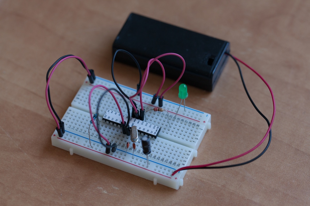
First, put the microcontroller in the center of the breadboard. You can then take care about the power: connect power lines on each side, connect the negative power rail to the two GND pins of the microcontroller, and the positive power rail to VCC, AVCC, and AREF. Also, add the 10uF capacitor between two power rails. Finally, add the battery to the system.
You also have to add the crystal between the X1 and X2 pins, with 22pF capacitors going from each pin to the ground. Also, you need to connect the RST pin to the positive power rail using a 10K Ohm resistor. To see if the system is working, connect the green LED in series with a 220 Ohm resistor to the digital pin 13 of the Arduino board, the other side going to the ground.
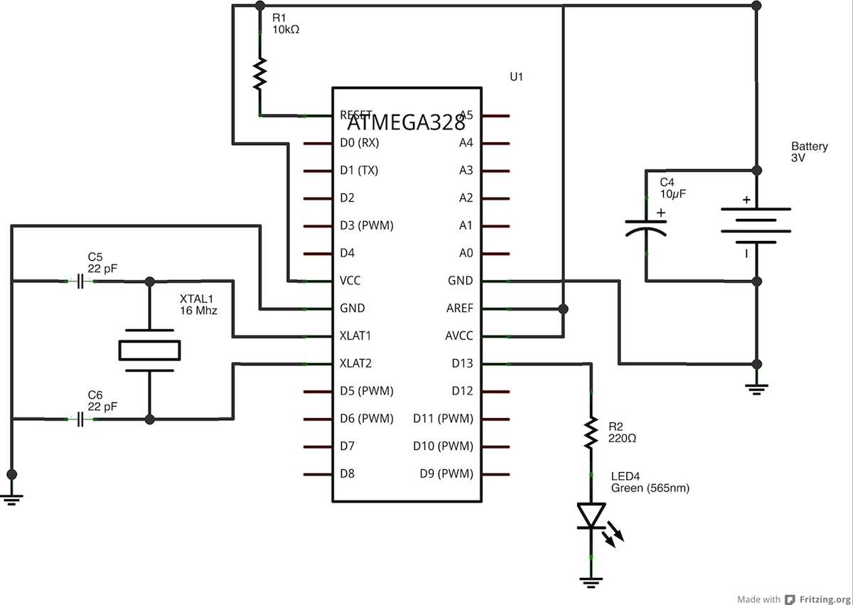
This is the complete schematics of the project:
Testing your Arduino system
It’s now time to test if the hardware part is working. What I did in this project is to use the Arduino Uno board to program the chip, and then I just “transplanted” the chip on the breadboard. You can just use the default “blink” sketch to program the microcontroller. After this is done, just replace the chip on the breadboard, and plug your battery (my battery pack even has a nice on/off switch). The LED should just goes on and off every second as expected.
Optimizing for Low-power
So now, we have an autonomous Arduino system. But it still consuming way too much power. Indeed, even when the LED is off, the Arduino chip is still active and consumes power. But there are functions on the microcontroller to put it to sleep during the time it is inactive, and re-activate the chip when we need to change the state of an output or to perform some measurements. I tested many solutions to really reduce the power to the lowest value possible, and the best I found is the JeeLib library. You can just download it and install it by placing the folder in your Arduino/libraries/ folder.
This is the sketch I used:
#include
ISR(WDT_vect) { Sleepy::watchdogEvent(); }
Sleepy::loseSomeTime(5000);
You basically just have to include the JeeLib library with:
#include
Then initialize the watchdog with:
ISR(WDT_vect) { Sleepy::watchdogEvent(); }
Finally, you can put the Arduino to sleep for a given period of time with:
Sleepy::loseSomeTime(5000);Upload the sketch with the Arduino IDE and replace the chip on the breadboard. You should see your Arduino having the same behavior as before (with 5 seconds intervals). But the difference is that now when the LED is off, the Arduino chip doesn’t use a lot of power. To finish this article, I wanted to actually quantify the power consumption of the system we just built. You can do the exact same by placing a multimeter between one of the power lines. For example, I connected the positive pin of the battery to one pin of my multimeter, and the other pin to the positive power rail of the breadboard. Here are the results:
- LED off, without the JeeLib library: 6.7 mA
- LED on, without the JeeLib library: 8.8 mA
- LED off, with the JeeLib library: 43 uA (!)
- LED on, with the JeeLib library: 2.2mA
From these results, we can see that our breadboard-Arduino consumes 6.7 mA when doing nothing without caring about putting it to sleep. For information, that will drain your two batteries in about a month. Which is actually not so bad, but we can do better. With the sleep functions, this can be reduced to 43 uA, which is a 150x improvement.
Let’s do some calculations to see how it will impact a real project, for example a temperature sensor. It takes about 500 ms to perform a measurement, at about 2.5 mA of current. Then, the systems sleeps for 10 seconds and the loop starts again. The “mean” is then 0.16 mA over a complete loop. With batteries rated at 2500 mAh, it means in theory the system will last … nearly 2 years without changing the batteries! Of course, some other effects will actually modify this number, but it gives you an idea.
How to Go Further
Really, you can adapt this idea to every system where the active time is small compared to the sleep time, and make your Arduino last for years without changing the battery!