Arduino WiFi Power Switch & Energy Monitoring Device

In this project, we are going to build an open-source version of WiFi power switches that you can buy in many stores. These switches can usually be controlled from a smartphone or tablet, and give you the ability to switch on or off any device that is connected to the switch. Sometimes, these switches also allow you to monitor the energy consumption of the device connected to the switch.
We are going to use Arduino, the CC3000 WiFi chip, a relay module and a current sensor to make an open-source version of such WiFi power switches. With the project we are going to build in this guide, you will be able to control this switch from your computer, or from any device connected to your local WiFi network.
You will be able to plug a 110v or 230v device into the switch (I took a standard 30W desk lamp as an example) and switch this device on or off via WiFi. Using the interface that we are going to build, you'll also be able to monitor the power consumption of the device that is connected to the switch.
What you'll need
Step by step
Hardware & Software Requirements
The first step is to get the required hardware components for the project. You need the following components to build this project:
- Arduino Uno
- 5V relay module
- ACS712 current sensor
- CC3000 WiFi breakout board
- Breadboard and jumper wires
For the Arduino board, I simply used an Arduino Uno R3 board. Then, for the relay module, I used a 5V relay module from Polulu, which nicely integrates a relay on a board, along with all the required components to control the relay from the Arduino board.

To measure the current flowing through the device connected to the switch, I used a board based on the AC712 sensor. This sensor returns an analog output that is proportional to the measured current.
For the WiFi module itself, I used the Adafruit CC3000 breakout board with the integrated antenna. Of course, you can also use the version of this board that uses an external antenna, or the CC3000 WiFi shield.
To connect to the lamp to the project, I used a standard pair of power plugs with bare cables at the end, with one female socket (to plug the lamp in) and one male socket (to plug it into the power socket in the wall).
Finally, I used a breadboard and some jumper wires to make the different electrical connections.
On the software side, you need to have the latest version of the Arduino IDE installed on your computer, as well as the aREST library for Arduino which you can find at: https://github.com/marcoschwartz/aREST
This project also requires having the CC3000 chip library: https://github.com/adafruit/Adafruit_CC3000_Library
And the CC3000 mDNS library: https://github.com/adafruit/CC3000_MDNS
You will also need to have Node.js installed on your computer. You can download it by going at: http://nodejs.org/
Hardware Configuration
Let's now assemble the hardware for this project. We will do so in two parts. We will first connect the different components like the relay module to the Arduino board, and then we will connect the power cables to the project.
The hardware connections for the first part are quite simple: we have to connect the relay module, the current sensor and the WiFi module. First, connect the Arduino Uno +5V pin to the red rail on the breadboard, and the ground pin to the blue rail.
Now, the WiFi module. First, connect the IRQ pin of the CC3000 board to pin number 3 of the Arduino board, VBAT to pin 5, and CS to pin 10. Then, you need to connect the SPI pins to the Arduino board: MOSI, MISO, and CLK go to pins 11, 12, and 13, respectively. Finally, take care of the power supply: Vin goes to the Arduino 5V (red power rail), and GND to GND (blue power rail).
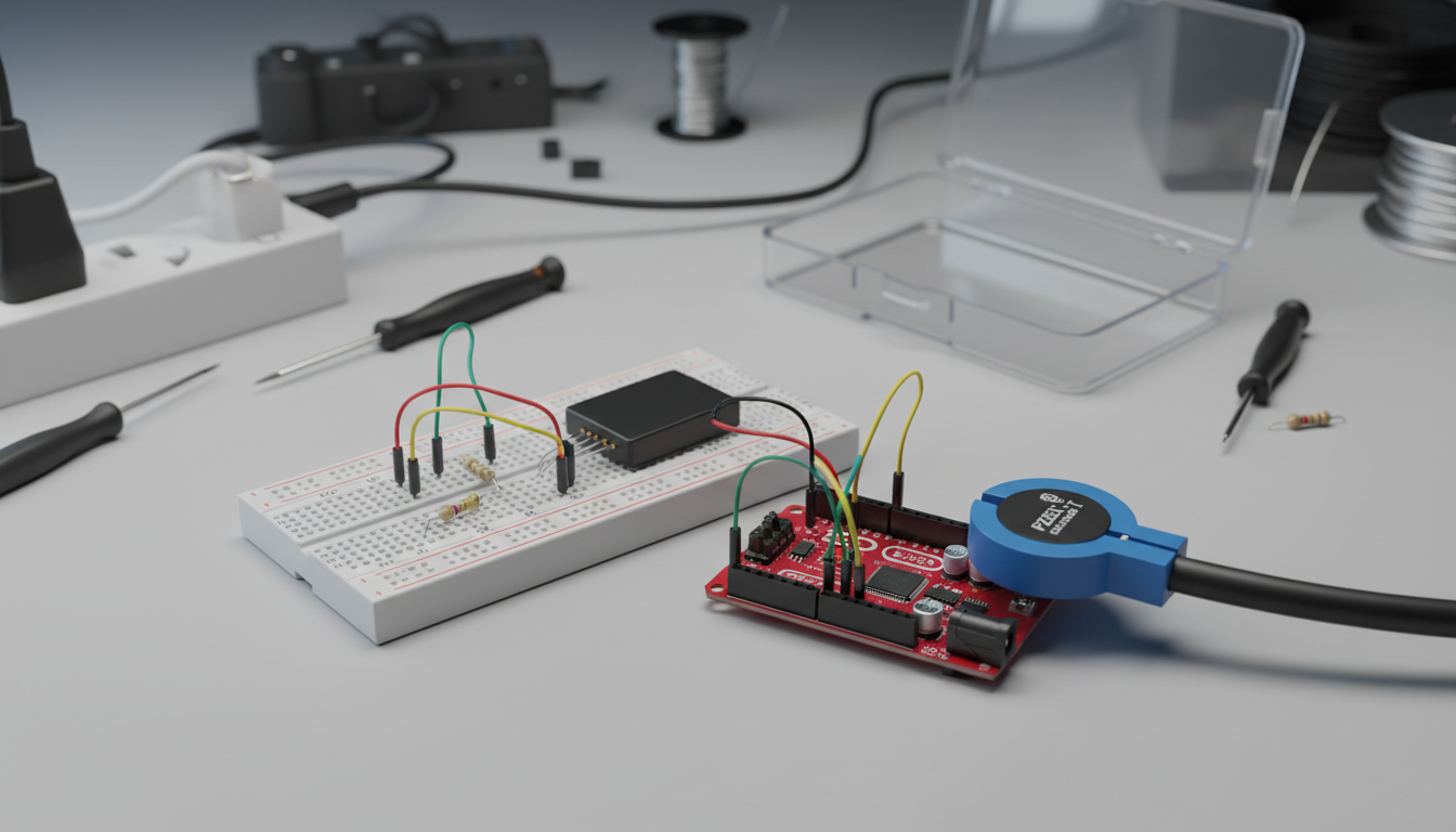
For the relay module, there are three pins you need to connect: VCC, GND and SIG. VCC needs to go the Arduino 5V pin, so connect it to the red power rail. GND goes to the Arduino ground pin, so to the blue power rail. Finally, connect the SIG pin to pin number 8 of the Arduino board.
It is actually similar for the current sensor module. It has three pins: VCC, GND, and OUT. As for the relay, VCC needs to go the Arduino 5V pin, so connect it to the red power rail. GND goes to the Arduino ground pin, so to the blue power rail. Then, connect the OUT pin to the analog pin A0 of the Arduino board.
We are now going to connect the lamp to the hardware we already assembled. Basically, the idea is to have the main power supply (coming from the power socket in the wall) going to the relay, then to the current sensor, and finally to the lamp.
Note that as this project involves dangerous voltages (110v or 230v), make sure that you never touch the project after having plugged it into an electrical socket. It is also recommend to put everything in a plastic enclosure when the project is in use.
Testing the Project
It is now time to test the project. As the most important part of the project is the relay module, that's what we are going to test here. We are simply going to switch the relay on and off continuously every 5 seconds, just to check that the relay is working. At this point, you can already plug a device (like the lamp I used as an example) into the project and connect the switch to an electrical socket, to see that all the connections are correctly made.
It starts by declaring on which pin the relay is connected to:
const int relay_pin = 8;
In the setup() function of the sketch, we set this pin as an output:
pinMode(relay_pin,OUTPUT);
Then, in the loop() function of the sketch, we set this pin to a HIGH state, switching on the relay:
digitalWrite(relay_pin, HIGH);
And wait for 5 seconds:
delay(5000);
We then switch the relay off again:
digitalWrite(relay_pin, LOW);
And wait for 5 seconds before repeating the loop() function:
delay(5000);
Note that you can find all the code for this part inside the GitHub repository of the project: https://github.com/openhomeautomation/arduino-wifi-switch
It's now time to test the sketch. Make sure that the lamp is correctly connected to the project, and that the male plug is plugged into the power socket in the wall. Then, upload the Arduino sketch to the board. You should see that every 5 seconds, the relay is switching, turning the device connected to it on and off.
Remote Control via WiFi
In this section, we are going to build the Arduino sketch that we will use to control the switch via WiFi, and also to get the power consumption of the device that is connected to the switch.
To do so, we are going to use the aREST library that implements a REST access to Arduino. This way, we can have an easy access to the pins of the Arduino board, and also to the variable in which the power measurement is stored.
It starts by including all the required libraries and declaring the pin on which the relay module is connected:
const int relay_pin = 8;
Then, we declare the different variables that are required for the power measurement part:
float amplitude_current;
float effective_value;
float effective_voltage = 230; // Set voltage to 230V (Europe) or 110V (US)
float effective_power;
float zero_sensor;
Then, we create the instance of the aREST object that we will use to handle the requests coming via the WiFi connection:
aREST rest = aREST();
We also need to define on which port we want to the WiFi chip to listen to. For convenience, we will use the port 80, so you can directly command your Arduino board from a web browser:
#define LISTEN_PORT 80
We also create an instance of the CC3000 server:
Adafruit_CC3000_Server restServer(LISTEN_PORT);
We also need to create an instance of the MDNS server, so we can send commands to the Arduino board without having to type the board IP address to access it:
MDNSResponder mdns;
Finally, we declare a variable that will contain the measurement of the power consumption:
int power;
Now, in the setup() function of the sketch, we first expose the measurement variable to the REST API so we can access it from the outside world via WiFi:
rest.variable("power",&power);
After that, we declare the relay pin as an output:
pinMode(relay_pin,OUTPUT);
We also use a function that averages the measurements of the current sensor to get the sensor's reading at which the current is null:
zero_sensor = getSensorValue(A0);
We can also set a name and an ID for the device, that will be returned at each call of the board via the aREST library:
rest.set_id("001");
rest.set_name("smart_lamp");
After this step, we set a name for the Arduino board on the network, for example "arduino". This means that the board will be accessible by the name arduino.local on your local network:
if (!mdns.begin("arduino", cc3000)) {
  while(1);
}
Finally, still in the setup() function we start the CC3000 server and wait for incoming connections:
restServer.begin();
Serial.println(F("Listening for connections..."));
In the loop() function of the sketch, we first get the reading coming from the current sensor, again by using a function to average the result over several measurements:
float sensor_value = getSensorValue(A0);
Then, we can calculate the power from the measured current:
amplitude_current = (float)(sensor_value-zero_sensor)/1024*5/185*1000000;
effective_value = amplitude_current/1.414;
effective_power = abs(effective_value*effective_voltage/1000);
power = (int)effective_power;
After that, we update the MDNS server:
mdns.update();
And process any incoming connection using the aREST library:
Adafruit_CC3000_ClientRef client = restServer.available();
rest.handle(client);
Note that you can find all the code for this part inside the GitHub repository of the project: https://github.com/openhomeautomation/arduino-wifi-switch
It's now time to test this sketch on our project. Download the code from the GitHub repository, and make sure that you modify the name and the password of the WiFi network on which the WiFi chip will connect to. Then, upload the code to the Arduino board, and open the Serial monitor.
Now, close the Serial monitor, and open your web browser. You can now make direct calls to the REST API running on the board to control the pins of the Arduino board. You should hear the relay switching, and have a confirmation message inside your browser.
Note that these commands will work from any devices connect to the same local network as the Arduino board. For example, you can use your smartphone to control your Arduino board with the same commands.
If it doesn't work, the first thing to do is to use the IP address of the board in place of the arduino.local name. You can get the IP address of the board by looking at the messages displayed on the Serial monitor when starting the project.
Building the Web Interface
We are now going to build the interface that you will use to control the project from your computer. Using this interface, you will be able to control the switch via WiFi, but also to see in real-time the power consumption of the device connected to it.
The interface we are going to develop is based on Node.js that will basically run a web server on your computer. You don't need to have any experience with Node.js to make this project work.
First, we are going to code the main file called app.js, which we will run later using the node command in a terminal. It starts by importing the required modules and create our app based on the express framework. We also set the port to 3700:
var express = require('express');
var app = express();
var port = 3700;
We specify that we will be using the Jade module, which is a templating engine for HTML:
app.set('view engine', 'jade');
We also need to tell our software where to find the CSS & JavaScript code for the interface:
app.use(express.static(__dirname + '/public'));
Now, we are going to build the different routes of our server. The first one concerns the interface itself:
app.get('/interface', function(req, res){
 res.render('interface');
});
We also use the aREST module, which will be used to access our WiFi Arduino device:
var rest = require("arest")(app);
rest.addDevice('http','192.168.1.102');
Finally, still in this app.js file, we start the app with the port we defined before:
app.listen(port);
console.log("Listening on port " + port);
This was for the main server file. Now, we are going to build the interface itself. Let's see the content of the Jade file first.
The file starts by importing the different JavaScript files that will handle the click on the interface, and send the correct commands to the Arduino board:
script(src="https://code.jquery.com/jquery-2.1.1.min.js")
script(src="/js/interface.js")
script(src="/js/ajaxq.js")
We also include some css files to give a better look at our interface:
link(rel='stylesheet', href="https://maxcdn.bootstrapcdn.com/bootstrap/3.3.0/css/bootstrap.min.css")
link(rel='stylesheet', href="/css/interface.css")
Then, we need to create two buttons: one to turn the relay on, and another one to switch it off again. Finally, we also need to create text fields to display the power measurement made by our Arduino project and an indicator to check that the project is online.
Now, we are going to see the contents of the interface.js file, located in the public/js folder of the project. Inside this file, we will handle what happens when a button is clicked in the interface. Depending on which button is clicked (identified by the id of the button), we send a different command to the Arduino board.
$("#1").click(function() {
  $.getq('queue', 'smart_lamp/digital/8/1');
});

$("#2").click(function() {
  $.getq('queue', 'smart_lamp/digital/8/0');
});
Then, we will define a function to refresh the power measurements & the status of our Arduino project:
function refreshPower() {
  $.getq('queue', 'smart_lamp/power', function(json_data) {
    $("#powerDisplay").html("Power: " + json_data.power + "W");
    if (json_data.connected == 1){
      $("#status").html("Device Online");
      $("#status").css("color","green");
    }
    else {
      $("#status").html("Device Offline");
      $("#status").css("color","red");
    }
  });
}

refreshPower();
setInterval(refreshPower, 5000);
Note that you can find all the code for this part inside the GitHub repository of the project: https://github.com/openhomeautomation/arduino-wifi-switch
It's now time to test the interface. Make sure that you download all the files from the GitHub repository, and update the code with your own data if necessary, like the Arduino board IP address. Also, make sure that the Arduino board is programmed with the code we saw earlier in this guide.
Then, go to the folder of the interface with a terminal, and install the required modules. Finally, you can start the Node.js server by typing the appropriate commands.
You can now go to your web browser and access the interface. You should see the interface being displayed inside your browser, with the buttons to control the switch. Don't worry, when you first open the interface the project should appear as offline and the indicator should not display any data. After loading the page, the interface will make a query to the Arduino board and update the data accordingly.
You can now also test the different buttons of the interface. By default, the switch is turned off, so click on the "On" button to turn it on instantly. You should also hear the "click" coming from the relay.
When the switch is on and you have a device connected to it, you should also see that the power measurement display is updated accordingly on the interface. Then, you can click on the "Off" button to switch it off again.
Wrapping up
How to Go Further
Let's summarise what we did in this guide. We learned how to build a power switch & energy monitoring device and to control it from your web browser. We were able to control a 110v or 230v device wirelessly, for example a lamp, and monitor its energy consumption via WiFi. Finally, we build a software running on your computer to control the whole project from a graphical interface within your web browser.
There are of course many ways to go further with this project. You can of course add more sensors to the Arduino board and access these measurements wirelessly. For example, you could perfectly add a temperature sensor to the project and display the data on the graphical interface as well. You can also add another switch (relay module and current sensor) to this project, and control both independently.
By changing the code running on your computer, inside the JavaScript file, you can also define more complex behaviours for the switch. Not only you can control the switch from the interface but you can also use the fact that your computer is connected to the web to create more complex behaviours. For example, you can automatically switch a lamp off after a given time in the evening, and switch it on again in the early morning to wake you up.
Finally, you can have several of these projects in your home, simply by giving different names to your Arduino boards, and adding more elements in the graphical interface. You can also create more behaviours and buttons for your project, for example a button to automatically switch off all devices in your home with a simple click.