Build an Arduino Power Meter with an OLED Screen (DC Version)
Controlling the electrical consumption in your home is one of the most important things you can do, both because of environmental concerns and to reduce the electricity bill at the end of the month. There are countless electrical power meters out there, but in this tutorial, I'll show you how to build your own and use Arduino to measure how much power a single device is using. Note that this tutorial is about measuring power for DC (Direct Current) devices only.
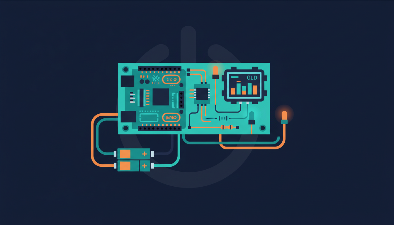
In this project, we'll measure the power used by a device and display it on a small OLED screen right next to the Arduino board. This way, you'll be able to build your own independent power meter based on Arduino that doesn't require any external components or internet connection. Let's start!
What you'll need
Step by step
Gather Hardware and Software Requirements
Let's first see what we need to build this project. As the center of the project, we'll use an Arduino Uno board, but you can use any other Arduino board. To measure the voltage and current of the measured device, we'll use an Adafruit breakout board for the INA219 sensor. To display the data, we'll use the Adafruit 128×64 OLED screen, as it has a very easy to use Arduino library.
As a test device, we'll use a simple LED along with a 330 Ohm resistor, but this could also be any DC device you are using in your home, for example a strip of LEDs. You'll also need the usual breadboard and jumper wires to make the necessary connections.
On the software side, you will need the latest version of the Arduino IDE. You will also need two libraries that you can install from the Arduino library manager: Adafruit_INA219 and Adafruit_SSD1306.
Assemble the Hardware Configuration
Now let's see how to assemble the hardware for this project. As there are a lot of connections to do, here's the layout:

For the INA219 sensor, you first need to connect the power (VCC and GND) to the Arduino Uno power. For convenience, connect the Arduino 5V and GND pins to the two power rails of the breadboard. Then, connect the SCL pin to Arduino pin A5, and the SDA pin to Arduino pin A4.
For the OLED screen, you will also need to connect the screen breakout board to the power rails (Vin and GND pins). Then, for the SDA and SCL pins (sometimes called Data and Clock), you can simply connect them to the same pins on the INA219 board. Finally, connect the CS pin to Arduino pin 4.
Finally, for the LED, we need to make the current of the LED flow through the INA219 sensor so it can be measured. To do so, first connect pin 7 of the Arduino board to the Vin+ pin of the sensor. Then, connect the Vin- pin of the sensor to the resistor, in series with the anode of the LED. Finally, connect the other pin of the LED to the ground. This is the final result:
Initialize Libraries and Create Sensor Instances
We start by importing the required libraries and creating instances for our sensors. First, include the necessary libraries at the top of your sketch:
#include <Wire.h>
#include <Adafruit_INA219.h>
#include <Adafruit_GFX.h>
#include <Adafruit_SSD1306.h>
Then, create an instance of the INA219 sensor:
Adafruit_INA219 ina219;Next, create an instance of the OLED screen:
#define OLED_RESET 4
Adafruit_SSD1306 display(OLED_RESET);
#if (SSD1306_LCDHEIGHT != 64)
#error("Height incorrect, please fix Adafruit_SSD1306.h!");
#endifConfigure Setup Function
Inside the setup() function of the sketch, initialize the sensor and the OLED screen:
// Init INA219
if (! ina219.begin()) {
  Serial.println("Failed to find INA219 chip");
  while (1) { delay(10); }
}
ina219.setCalibration_16V_400mA();

// Init OLED
display.begin(SSD1306_SWITCHCAPVCC, 0x3D);

// Display welcome message
display.clearDisplay();
display.setTextSize(2);
display.setTextColor(WHITE);
display.setCursor(0, 26);
display.println("Ready!");
display.display();
delay(1000);

// LED
pinMode(7, OUTPUT);
Note that we also set pin 7 as an output, as we'll use it to turn the LED on and off.
Implement Power Measurement Function
Create a function to measure the power consumption of the connected device:
float measurePower() {
  // Measure
  float shuntvoltage = ina219.getShuntVoltage_mV();
  float busvoltage = ina219.getBusVoltage_V();
  float current_mA = ina219.getCurrent_mA();
  float loadvoltage = busvoltage + (shuntvoltage / 1000);

  Serial.print("Bus Voltage:   ");
  Serial.print(busvoltage);
  Serial.println(" V");
  Serial.print("Shunt Voltage: ");
  Serial.print(shuntvoltage);
  Serial.println(" mV");
  Serial.print("Load Voltage:  ");
  Serial.print(loadvoltage);
  Serial.println(" V");
  Serial.print("Current:       ");
  Serial.print(current_mA);
  Serial.println(" mA");
  Serial.println("");

  // If negative, set to zero
  if (current_mA < 0) {
    current_mA = 0.0;
  }

  return current_mA * loadvoltage;
}
This function reads the voltage and current from the INA219 sensor and calculates the power consumption by multiplying current by voltage.
Create Display Function
Create a function to display the measured data on the OLED screen:
void displayData(float current, float power) {
  // Clear
  display.clearDisplay();
  display.setTextSize(2);
  display.setTextColor(WHITE);

  // Current
  display.setCursor(0, 0);
  display.println("Current: ");
  display.print(current);
  display.println(" mA");

  // Power
  display.println("Power: ");
  display.print(power);
  display.println(" mW");

  // Display on screen
  display.display();
}
This function clears the display, sets the text properties, and then displays both the current and power values in a clear format.
Implement Main Loop
In the loop() function, alternate between turning the LED off and on while measuring power consumption:
float current_mA = 0;
float power_mW = 0;

void loop() {
  // LED OFF
  digitalWrite(7, LOW);

  // Measure
  current_mA = ina219.getCurrent_mA();
  power_mW = measurePower();

  // Display data
  displayData(current_mA, power_mW);
  delay(2000);

  // LED ON
  digitalWrite(7, HIGH);

  // Measure
  current_mA = ina219.getCurrent_mA();
  power_mW = measurePower();

  // Display data
  displayData(current_mA, power_mW);
  delay(2000);
}
The loop alternates between turning the LED off and on with a 2-second delay, continuously measuring and displaying the power consumption.
Test and Verify Results
Now it's time to test the project! Grab the whole code, open it into your Arduino IDE, and upload the code to the board. You should first see that the LED is off, and also see the readings on the OLED screen:

It makes complete sense that the current and power used by the LED are null, as the LED is off.
After a few seconds, the LED should then turn on, and you should instantly see the current and power used by the LED:
If your readings look correct, congratulations! You have successfully built your Arduino power meter.
Wrapping up
Congratulations, you just built a DC power meter using Arduino that can display measurements on an OLED screen! You can now take what you learned in this tutorial and use it in several other projects. You can use this project on multiple devices in your home and have them all display the current power used by each device. You can also add wireless connectivity to send measurements to a cloud platform like aREST.