Build Your Own Arduino Breathalyzer
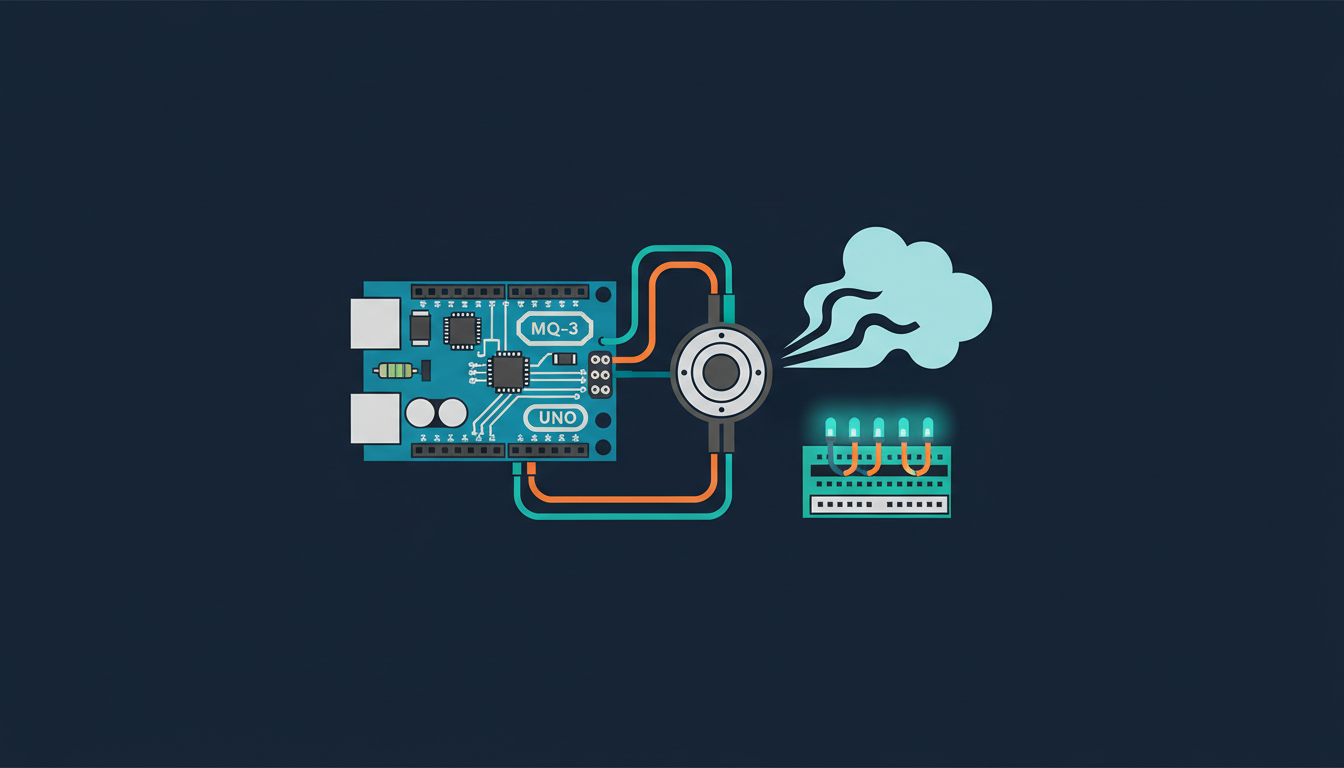
In this article, we are going to use the Arduino platform to build a really cool project: your very own alcohol breathalyser. To do that, we are going to use a simple Arduino Uno board, along with an ethanol gas sensor, to sense the level of alcohol in your breath. To display the results, we will use an LCD screen. As the 'interface' with the system, we will just use a simple push button and a piezo buzzer.
Note that because of possible sensor calibration issues, this project should be used for educational purposes only, and not to determine your real alcohol blood levels before driving for example. Let's start!
What you'll need
Step by step
Hardware & Software Requirements
Let's first see what we need for this project. We will of course need an Arduino Uno board, that will be the 'brain' of the project.
Then, we will need a sensor to measure the alcohol levels in your breath. Here, I used an MQ-3 ethanol sensor, mounted on a breakout board:
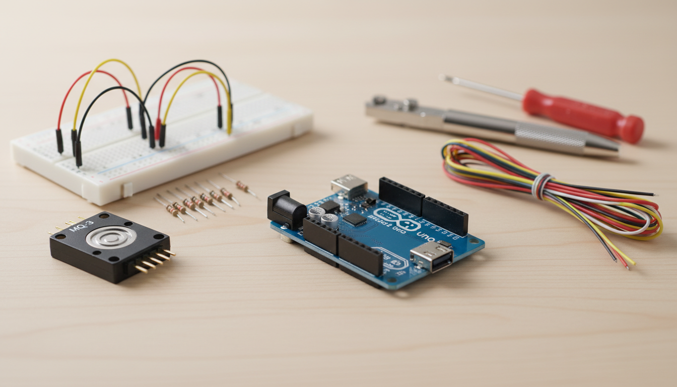
As the interface for the project, we will also use a push button (with a 10k Ohm resistor) and a piezo buzzer. I also used an I2C LCD screen to display the results.
Finally, you will also need a breadboard and a bunch of jumper wires.
On the software side, you will need the latest version of the Arduino IDE, as well as the I2C LCD library that you can get using the library manager from the Arduino IDE.
Hardware Configuration
Let's now assemble the project. This is a top view showing all the connections between the components of the project:

Let's see how to assemble the different parts of the project. First, let's connect the power supply from the Arduino board to the breadboard. Connect the Arduino 5V pin to the red power rail of the breadboard, and the GND pin to the blue power rail of the breadboard.
For the MQ-3 sensor, connect the VCC pin to the red power rail, the GND pin to the blue power rail, and finally the signal pin to analog pin A0 of the Arduino board.
For the push button, connect one side of the button in series with the 10k Ohm resistor. Then, connect this side as well to pin 2 of the Arduino board. Then, connect the other side of the resistor to the ground, and the other side of the button to VCC.
For the piezo buzzer, connect the + pin on pin 7 of the Arduino board, and the other pin on the ground.
Finally, connect the LCD screen using the I2C interface (SDA and SCL on the Arduino board).
This is the picture of the completely assembled project:
Building the Code for the Project
We are now going to write the code for the project. Here, we are simply going to go over the most important parts of the code. You will be able to find the complete version of the code later on the GitHub repository of the project.
First, we declare the libraries that are necessary for the LCD screen:
#include <LiquidCrystal_I2C.h>We declare a warmup time of 20 seconds for the MQ-3 sensor, which is necessary for a good functioning of the sensor:
int TIME_UNTIL_WARMUP = 20;
unsigned long time;
We also declare a time for each measurement, which is basically the time for which the user will have to blow on the sensor for the measurement:
int TIME_UNTIL_MEASURE = 5;
unsigned long measurement_start;
Then, we declare the pin of the MQ-3 sensor, and we initialise the value of the sensor to 0:
int analogPin = A0;
int val = 0;
We also declare the pin of the piezo buzzer:
const int buzzerPin = 7;
And the pin of the push button:
const int buttonPin = 2;
Then, we initialise the I2C LCD instance:
LiquidCrystal_I2C lcd(0x27,20,4);In the setup() function of the sketch, we initialise the LCD screen, and activate the backlight:
lcd.init();
lcd.backlight();
In the loop() part of the sketch, we check if the button was pressed. If that's the case, we reset the whole measurement process:
int button_state = digitalRead(buttonPin);

if (button_state && !measurement_mode) {
  lcd.clear();
  measurement_mode = true;
  measurement_start = millis()/1000;
  measurement_done = false;
}
We also keep track of the time with a counter:
time = millis()/1000;
If we are still in the warmup process, we wait, and print this status on the LCD screen:
if(time<=time_until_warmup) {
  printwarming(progress_time);
}
Once the warmup is done, we wait until the user press the button to start the measurement process:
else
{
  if (measurement_mode == false && !measurement_done) {
    printPress();
  }
  if (measurement_mode && !measurement_done) {
    printMeasure();
    tone(buzzerPin, 1000);
    val = readAlcohol();
  }
  if (measurement_mode && !measurement_done && ((time - measurement_start)> TIME_UNTIL_MEASURE)){
    noTone(buzzerPin);
    measurement_mode = false;
    measurement_done = true;
    lcd.clear();
  }
  if(measurement_done) {
    printAlcohol(val);
    printAlcoholLevel(val);
  }
}
Testing The Breathalyzer
Let's now test the project. Make sure that you made all the correct hardware connections. Then, open the code with the Arduino IDE, and upload it to the board.
Then, you should see the warming up part of the sketch, indicating the sensor is initializing. The project will then ask you to press the button to start.
You can then breathe into the sensor until you don't hear the sound from the buzzer anymore.
After that, you will get the reading, and also a message indicating if you are sober or not (according to the threshold you set in the code).
Congratulations, you just build your own breathalizer based on Arduino!
How to Go Further
In this project, we built a very simple breathalizer project based on Arduino, using a MQ-3 Ethanol sensor. Of course, the next step would be to really carefully calibrate the sensor so it can give more accurate readings. If you did such calibration step with your project, please share below!
Wrapping up
You have successfully built your own Arduino-based breathalyzer! This project demonstrates practical applications of Arduino microcontrollers, sensor interfacing, and user interaction through buttons and feedback mechanisms. While this educational version provides a foundation for understanding alcohol vapor detection, remember that real breathalyzers require precise calibration for accurate results. You can further enhance this project by implementing data logging, wireless connectivity, or integrating additional sensors for improved accuracy.